

|
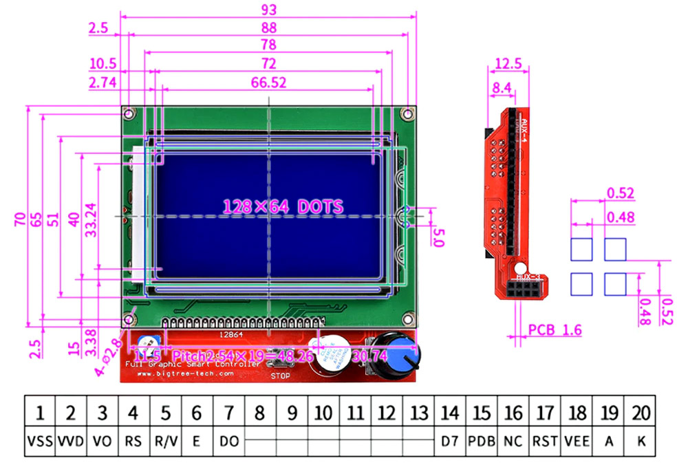
LCD 128x64 3D Ramps |
- LCD 128x64 3D Ramps cho máy CNC, in 3D được thiết kế để sử dụng với Board Ramps có chức năng làm bảng hiển thị và điều khiển cho máy in 3D.
- Mạch có tích hợp khe cắm thẻ nhớ SD, cần điều khiển rotary encoder với nút bấm, cho phép cân chỉnh từ việc di chuyển các trục và nạp G-code trực tiếp từ khe cắm thẻ nhớ.
- Sử dụng thẻ nhớ để lưu và nạp code khi vận hành giúp máy in hoạt động độc lập; không phụ thuộc vào máy tính qua cổng USB.
- Sử dụng màn hình LCD 128x64 để hiển thị và điều khiển các chức năng của máy in bằng nút điều khiển ngay trên máy giúp việc kiểm tra, bảo dưỡng máy thuận tiện, nhanh nhóng, chuyên nghiệp.
- Bộ hiển thị LCD/ SD card sử dụng với các máy in 3D; Với board Mạch điều khiển máy in 3D RAMPS 1.4 hoặc các phiên bản của board MKS based.
- Mạch được thiết kế để cắm vào RAMPS hoặc các loại Ultimaker breakboard shield để điều khiển máy in 3D một cách trực tiếp.
Thông số kỹ thuật:
- Sử dụng với mạch RAMPS 1.4
- Điều khiển bằng biến trở encoder có nút nhấn
- Hỗ trợ in 3D, đọc gcode từ thẻ nhớ
- Thẻ nhớ tương thích: SD Memory Card
- Có còi bíp
- Nút Stop hỗ trợ ngừng khẩn cấp
|
LCD 128x64 3D Ramps |
|
Bảng này phù hợp cho cấu hình bên dưới |
Thiết kế gốc và Bản sao/Biến thể:
Thiết kế ban đầu hỗ trợ giao tiếp Song song 8 bit và giao tiếp nối tiếp 4 bit. Nhiều bản sao hoặc biến thể chỉ hỗ trợ giao tiếp nối tiếp (SPI).
Các biến thể của thiết kế có thể có quạt hoặc loại bỏ Thẻ SD, trong số những thay đổi khác.
Một số bản sao có thể gặp sự cố do hạn chế về thời gian với màn hình được sử dụng.
Tùy thuộc vào nhà cung cấp, bạn có thể tìm thấy các bo mạch sử dụng Trình điều khiển IC ST7920, Trình điều khiển IC ST7565 hoặc loại khác. Các bo mạch sử dụng Màn hình DOG-M128 sử dụng Trình điều khiển IC ST7565. Các bảng chung và phổ biến hơn sử dụng một số hương vị của màn hình LCD 12864 với ST7920, đây là trường hợp của hầu hết các bảng bạn tìm thấy trong các cửa hàng trực tuyến.
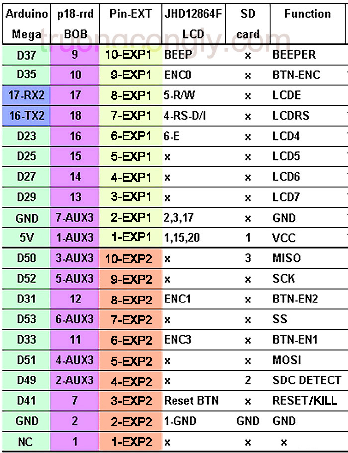
Kết nối:
Bo mạch có hai đầu nối 10 chân (2 hàng với bước 2,54mm) được đánh dấu EXP1 và EXP2 (ĐẦU NỐI IDC 10 CHÂN). Hình dưới đây cho thấy ánh xạ sơ đồ chân tới Arduino Mega 2560:

|
smart adapter |
Bản sao và các nhà sản xuất khác có thể cung cấp các kết nối khác nhau, đặc biệt là các mẫu không có Thẻ SD hoặc các mẫu chỉ hỗ trợ SPI
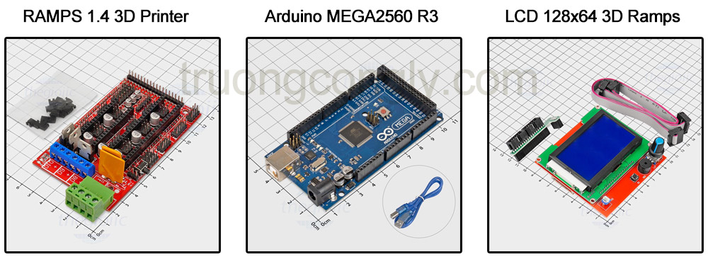
Phần cứng cần thiết:
Code Test:
/* Include the UG8lib Library */
#include <U8glib.h>

/* Include the SD card library */
#include <SD.h>

/* DIO pin used to control the SD card readers CS pin */
#define SD_CARD_CD_DIO 53

/* Rotary encoder (dial) pins */
#define ROT_EN_A 31
#define ROT_EN_B 33

/* Rotary encoder button pin */
#define BUTTON_DIO 35
#define BUZZER_DIO 37

/* Stop button pin */
#define STOP_DIO 41

/* LCD display pins */
#define LCD_RS 16
#define LCD_EN 17
#define LCD_D4 23
#define LCD_D5 25
#define LCD_D6 27
#define LCD_D7 29


/* Create an instance of the LCD library. */
U8GLIB_ST7920_128X64_1X u8g(23, 17, 16);

/* Create an instance of the SD card library */
File SDFileData;


void setup()
{
  /* Configure the pins used to read the status of the panel dial
     and buttons */
  pinMode(BUZZER_DIO, OUTPUT);
  pinMode(BUTTON_DIO, INPUT);
  digitalWrite(BUTTON_DIO, HIGH);
  pinMode(STOP_DIO, INPUT);
  digitalWrite(STOP_DIO, HIGH);
  pinMode(ROT_EN_A,INPUT);
  pinMode(ROT_EN_B,INPUT);
  digitalWrite(ROT_EN_A, HIGH);
  digitalWrite(ROT_EN_B, HIGH);
}


/* Main program loop */
void loop()
{

  /* Output the test message to the LCD */
  u8g.setFont(u8g_font_helvB08);
  u8g.firstPage();
  do
  {
    u8g.drawStr( 5, 10, "HOBBY COMPONENTS");
    u8g.drawStr( 15, 28, "RAMPS LCD PANEL");
    u8g.drawStr( 30, 44, "HC3DPR0006");
    u8g.drawStr( 48, 58, "TEST");
  }while(u8g.nextPage());

  /* Wait 4 seconds */
  delay(4000);

  /* Buzzer test */
  BuzzerCheck();

  /* SD card read test */
  SDCardCheck();
  delay(4000);

  /* Control check */
  ControlCheck();
  delay(4000);

  /* All done! */
  u8g.firstPage();
  do
  {
    u8g.drawStr( 20, 32, "TEST COMPLETE!");
  }while(u8g.nextPage());

  while(1);
}

/* Test the buzzer by beeping twice */
void BuzzerCheck(void)
{
  u8g.firstPage();
  do
  {
    u8g.drawStr( 25, 32, "BUZZER CHECK");
  }while(u8g.nextPage());

  delay(500);
  digitalWrite(BUZZER_DIO, HIGH);
  delay(300);
  digitalWrite(BUZZER_DIO, LOW);
  delay(300);
  digitalWrite(BUZZER_DIO, HIGH);
  delay(300);
  digitalWrite(BUZZER_DIO, LOW);
}

/* Test the SD card by reading the contents of a file named test.txt */
void SDCardCheck(void)
{
  byte index;
  char SDCardText[]= "                    ";

  u8g.firstPage();
  do
  {
    u8g.drawStr( 22, 10, "SD CARD CHECK");
    u8g.drawStr( 0, 28, "Initiliasing..");
  }while(u8g.nextPage());

  /* Initialise the SD card */
  if (!SD.begin(SD_CARD_CD_DIO))
  {
    u8g.firstPage();
    do
    {
      u8g.drawStr( 22, 10, "SD CARD CHECK");
      u8g.drawStr( 0, 28, "Initiliasing..");
      u8g.drawStr( 0, 44, "ERROR!");
      u8g.drawStr( 0, 58, "SD Card not detected");
    }while(u8g.nextPage());
  }else
  {
    u8g.firstPage();
    do
    {
      u8g.drawStr( 22, 10, "SD CARD CHECK");
      u8g.drawStr( 0, 28, "Initiliasing..");
      u8g.drawStr( 0, 44, "OK!");
    }while(u8g.nextPage());
  }

  delay(2000);

   /* Check if the text file exists */
   if(SD.exists("test.txt"))
   {
     /* The file exists so open it */
     SDFileData = SD.open("test.txt");

     /* Sequentially read the data from the file and store the first 20 characters */
     for (index = 0; index < 20; index++)
     {
       if (SDFileData.available())
         SDCardText[index] = SDFileData.read();
     }

     u8g.firstPage();
     do
     {
       u8g.drawStr( 0, 10, "test.txt contents:");
       u8g.drawStr( 0, 44, SDCardText);
     }while(u8g.nextPage());
   }else
   {
     u8g.firstPage();
     do
     {
       u8g.drawStr( 0, 10, "test.txt missing");
     }while(u8g.nextPage());
   }

   /* Close the file */
   SDFileData.close();
}

/* Check the dial and push buttons */
void ControlCheck(void)
{
  byte DialPos = 0;
  byte Last_DialPos = 0;
  byte DialCount = 0;
  char number[] = "0123456789";

  /* Prompt the user to press the dial */
  u8g.firstPage();
  do
  {
    u8g.drawStr( 22, 10, "SD CARD CHECK");
    u8g.drawStr( 0, 28, "Press the dial..");
  }while(u8g.nextPage());

  /* Wait for the dial to be pressed */
  while(digitalRead(BUTTON_DIO));

  u8g.firstPage();
  do
  {
    u8g.drawStr( 48, 32, "PASS");
  }while(u8g.nextPage());

  delay(4000);

  /* Prompt the user to press the button marked stop */
  u8g.firstPage();
  do
  {
    u8g.drawStr( 0, 28, "Press the STOP button..");
  }while(u8g.nextPage());

  /* Wait for button to be pressed */
  while(digitalRead(STOP_DIO));

  u8g.firstPage();
  do
  {
    u8g.drawStr( 48, 32, "PASS");
  }while(u8g.nextPage());

  delay(4000);

  /* Prompt the user to turn the dial clockwise by 10 positions */
  u8g.firstPage();
  do
  {
    u8g.drawStr( 15, 28, "Rotate Dial CW...");
  }while(u8g.nextPage());

  /* Run this loop until the dial is turned 10 positions */
  while(DialCount <= 9)
  {
    /* Read the status of the dial */
    DialPos = (digitalRead(ROT_EN_B) << 1) | digitalRead(ROT_EN_A);

    /* Is the dial being turned clockwise ? */
    if (DialPos == 3 && Last_DialPos == 1)
    {
      /* If so increase the dial counter and display it */
      DialCount++;
      PintNumber(DialCount);
    }

    /* If the dial counter reaches a value of 10 then the test has passed */
    if (DialCount >= 10)
    {
      u8g.firstPage();
      do
      {
        u8g.drawStr( 48, 32, "PASS");
      }while(u8g.nextPage());
    }
    /* Remember the last position of the dial so we know when it has changed */
    Last_DialPos = DialPos;
  }

  delay(4000);
  DialCount = 10;

  /* Now instruct the user to rotate the dial counter-clockwise */
  u8g.firstPage();
  do
  {
    u8g.drawStr( 15, 28, "Rotate Dial CCW...");
  }while(u8g.nextPage());

  /* Run this loop until the dial is turned 10 positions */
  while(DialCount)
  {
    /* Read the status of the dial */
    DialPos = (digitalRead(ROT_EN_B) << 1) | digitalRead(ROT_EN_A);

    /* Is the dial being turned counter-clockwise ? */
    if (DialPos == 3 && Last_DialPos == 2)
    {
      /* If so decrease the dial counter and display it */
      DialCount--;
      PintNumber(DialCount);
    }

    /* If the dial counter reaches a value of 0 then the test has passed */
    if (DialCount == 0)
    {
      u8g.firstPage();
      do
      {
        u8g.drawStr( 48, 32, "PASS");
      }while(u8g.nextPage());
    }
    /* Remember the last position of the dial so we know when it has changed */
    Last_DialPos = DialPos;
  }
}

/* Prints a number to the display via the UG8lib library*/
void PintNumber(byte number)
{
  u8g.setFont(u8g_font_helvB14);
  u8g.firstPage();
  do
  {
    switch(number)
    {
       case 0:
         u8g.drawStr( 56, 362, "0");
         break;
       case 1:
         u8g.drawStr( 56, 36, "1");
         break;
       case 2:
         u8g.drawStr( 56, 36, "2");
         break;
       case 3:
         u8g.drawStr( 56, 36, "3");
         break;
       case 4:
         u8g.drawStr( 56, 36, "4");
         break;
       case 5:
         u8g.drawStr( 56, 36, "5");
         break;
       case 6:
         u8g.drawStr( 56, 36, "6");
         break;
       case 7:
         u8g.drawStr( 56, 36, "7");
         break;
       case 8:
         u8g.drawStr( 56, 36, "8");
         break;
       case 9:
         u8g.drawStr( 56, 36, "9");
         break;

     }
  }while(u8g.nextPage());
  u8g.setFont(u8g_font_helvB08);
}

/* FILE:    RAMPS_Graphic_LCD_Panel_Test
This sketch will test all of the components of the RAMPS compatible graphic LCD panel.
It assumes that the panel will be connected to an Arduino Mega and RAMPS shield.
However this sketch is useful if you are not intending to use it with a 3D printer
as an example of how to access the various components.

To run this test you will need to insert and SD card with a text file named
'test.txt'. The test will display on the LCD the first 20 characters contained
within this file. You will also be prompted, via the LCD screen, to adjust the
controls of the panel.

The sketch will perform the following tests:

Buzzer test: The buzzer will beep twice
SD Card test: Will attempt to read the contents of the test.txt file on the SD card
Dial button check: Will prompt you to press the panels dial
Reset button test: Will prompt you to press the button labelled reset on the panel
Dial CW rotate test: Will prompt you to turn the dial clockwise until count = 10
Dial CCW rotate test: Will prompt you to turn the dial counter-clockwise until count = 0

There will be a 4 second delay between each test.


You may copy, alter and reuse this code in any way you like but please leave
reference to hobbycomponents.com in your comments if you redistribute this code.
This software may not be used by other sellers.

THIS SOFTWARE IS PROVIDED "AS IS". HOBBY COMPONENTS LTD MAKES NO WARRANTIES, WHETHER
EXPRESS, IMPLIED OR STATUTORY, INCLUDING, BUT NOT LIMITED TO, IMPLIED WARRANTIES OF
MERCHANTABILITY AND FITNESS FOR A PARTICULAR PURPOSE, ACCURACY OR LACK OF NEGLIGENCE.
HOBBY COMPONENTS LTD SHALL NOT, IN ANY CIRCUMSTANCES, BE LIABLE FOR ANY DAMAGES,
INCLUDING, BUT NOT LIMITED TO, SPECIAL, INCIDENTAL OR CONSEQUENTIAL DAMAGES FOR ANY
REASON WHATSOEVER.
*/
Nhận xét